

Students explore the electronics and engineering of solar cells and then design and construct a solar panel.
QUESTION
How can solar cells be connected to make a solar panel for specific purpose?
Background
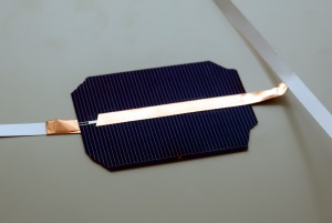
Silicon solar cells are the most widely used photovoltaic material. A single cell consists of a slab of silicon (single crystal or polycrystalline) with a continuous metal collector on the back and a grid contacts on the front which are necessary to collect the current from the wide area of the cell because silicon is a semiconductor which has a relatively high resistance compare to the silver contacts in the grid. A single cell produces about .55 V and a current depending on the area. Cells can be connected in series (front to back, front to back) in which case the voltage is added. When connected in parallel ( all the backs connected, all the fronts connected) the current of each cell is added and the voltage is same as any single cell. A combination of series and parallel circuits can be used to create a power source to match a particular application. Commercial panels are connected with flat tabbing wire that is soldered to make a permanent connection. Soldering solar cells is a delicate process that requires skill and practice. For these demonstration panels we can use copper tape with conducting adhesive.
Objectives
- Understand the role that photovoltaics can play in our energy future
- Experiment with solar cells and meters to discover and construct circuit rules
- Use terminology of electricity volts, amps, watts in context
- Use series and parallel circuits to design an arrangement
- Gain experience with the engineering design cycle
- Practice skills of soldering and work carefully to build a working device

Single cell solar panel with clip leads
Materials
- Small Unmounted Solar Cells (0.5V 1.8W silicon solar cells work well)
- Copper Foil tape or Tabbing Wire
- Clip Leads
- Foam Core or Plastic Backing Material
- Electric Meter or Motor to Test Cells
- Clear Laminating Film
Procedure
- Introductory Slide Show- (refer to sections after completing each activity- let students discover design principles by experimentation if possible.)
- Solar Cell Exploration-
- Measure the voltage of a variety of solar cells, under a light bulb, in the sun, try covering parts of the cell in one direction and then the other,
- Tilting the cells with respect to light source while measuring angle and voltage. Discuss what you have learned about the cells. Record observations on the data sheet.
- Series and parallel circuits- use the encased mini cells to try different circuits- measure voltage and current
- Try unequal size cells in series and parallel = (parallel tracks must have same area)
- Measure current from cell with a diode placed in different orientations
- Discussion of results and continue presentation presenting rules.
- Power calculations- Discuss definition of power and generate example of power requirements of different common devices. Calculate the power of sample cells and panels using the formula- P=I X V. Estimate number of cells
- Panel Design- Define the use you intend to make of the panel. Select the cells and draw a schematic of how the cells will be arranged. Use the worksheet to calculate the voltage and current that you expect your panel to generate in full sun
Build a Simple Solar Panel
- Place the unmounted cell flat on a hard smooth surface.
- Cut the clip leads in half and skin the insulation from the last 2 inches of each wire. You may twist the wire strands to make them stay straight.
- Cut two pieces of ¼ conductive copper foil tape 2” long. Remove the adhesive backing and attach it to the skinned end of one wire. Position this over the conductive strip on the back of the cell. Gently tape the wire down so that it has maximum contact with the soldering strip.
- Flip the cell over fix the other wire to the top. Be careful when smoothing that you don’t make uneven pressure due to the wire on the other side.
- Position the cell on a piece of foam core or rigid polystyrene.
- Place a piece of clear laminating plastic over the cell and smooth it down being careful to smooth out air bubbles and using the plastic to secure several inches of the clip lead to the cell.
Variations
- You can connect the cells with copper tape and then connect the output wires to the free end of the copper tape using solder or by wrapping the bare wire around the copper tape several times to get a good mechanical connection, copper to copper.
- To make a series panel with multiple cells use conductive copper tape to connect the front of one cell to back of another. It is necessary to half twist the tape as it comes off the back of one cell so that the sticky side can face the top of the next cell. The series circuit will add the voltage of each cells but will have a current equal to the smallest piece. So it does no good to combine small and large pieces in series. In a parallel circuit all the voltage is that of a single cell but the current of each is added regardless of size.
- Use double sided conductive tape or liquid “wire glue to attach cells from the top of one to the back of the other. The hard part about using scraps is that they often lack the solder header on the top of the cell that connects to the all the fine grid lines. Try to get take advantage of any solder strips that are present in order to decrease resistance.


** Wire glue is a thick paste that contains conductive carbon in a water soluble binder. You can apply drops of the wire glue at each interface point. This makes a good contact and decreases the chance of shattering cells as you press down.
Soldered Panel
- Rather can copper tape, you will need: soldering iron (Hobbico sells a reasonable 40W soldering iron), solder, solder flux (like Kester 186 Liquid Soldering Flux), and tab wire (pre-tinned if possible).
- Arrange the solar cells in the pattern you have chosen on a rigid backing material such as plexiglass or plywood. Pick smaller cells of the same size.
- Layout the pieces and cut lengths of tabbing wire.
- Soldering- practice on scraps and then carefully build a panel. Use lead free solder and wash your hands after handling the tabbing wire. Most solar cells have some white spots on the back which are solderable. Clean the solder strips with fine sandpaper. Apply liquid rosin to the spots where you will solder.
- You should be able to wet the solder strips with solder before placing the tabbing wire. Draw the soldering iron slow and steady along the pre-tinned tabbing wire allowing to melt the solder and bond with the solder strip below. Hold it down with a pencil lead. You may have to stop and let the soldering iron tip heat up between lengths. On the front solder to the wide collector ribbon. Flip the cell over and solder another piece of tabbing wire to the other side. Test connections as you go and test the whole thing before housing it.
- To make a complete charger add a 3 Amp diode to circuit in the right direction. The striped end of the diode is the cathode, the other end is the anode. The anode should be connected to positive side of the cell (the back).
- Housing- use hot glue to secure the cell array at a few spots. Solder to the flat ribbon to regular insulated wire with an extra bend and extra glue so it can’t pull loose. Use a dab of hot glue at each corner then gentile press the top plate down without crushing the cells. Apply clear packing tape to the edges to seal the unit.
- Try it out.
Vocabulary
- Solar cell- a single wafer having the characteristic voltage of the basic material
- Solar panel- an array of many solar cells, wired in series and parallel and usually encapsulated in a durable container to protect the cells
- Diode- and electronic device which allows current to flow in only one direction. This is a necessary part of a battery charging circuit to prevent the battery from discharging into the solar panel at night.
- Semiconductor- a type of material which conducts electricity under some conditions but not others
- Power- the rate of total energy flow – equal to volts x amps- measured in watts
- Voltage- the potential difference or electromotive force- measured in volts
- Current- the flow of electrons over time measured in amps
- Kilowatt hour- an amount of energy equivalent to 1000 watts expended for one hour.
- Parallel circuit- an arrangement in which electricity can flow through more than one path to the same destination
- Series circuit- an arrangement in which all electricity must flow through the same single path.
Resources
Resources
Wire Glue Conductive Adhesive (can connect cells that are sandwiched in series)
Diodes– 3 am 20 pack